


Let’s face it, security gives you a lot to think about. That can be especially frustrating when you’re just starting out and have not yet built a solid foundation in the basics. This is Part 1 of a two-part networking foundation for the Essentials series. It joins the Linux and Windows material behind the map-and-floor entrance and assumes only that you have an evening to spare and access to a free lab.
Part 1 covers the mechanics under network security: addressing, switching, routing, the access layer, and the routed boundaries where policy gets its first chance. Part 2 follows the security in motion through network services, monitoring, wireless, remote access, and the paths these skills open.
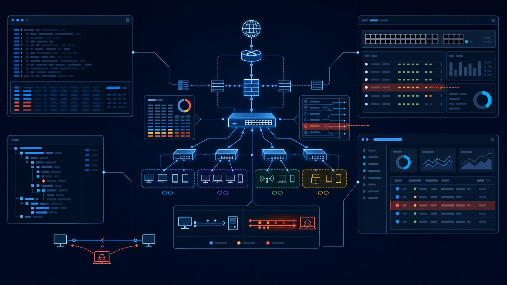
Each part can stand alone. Together they make one promise and pay it with the same picture.
Network security is controls placed where traffic must pass. A firewall rule, VLAN boundary, port-security limit, and access control list all depend on the same condition: traffic must cross a point you own. At that point, you decide what happens.
The problem starts when you cannot trace the path. You cannot place a control on a route you do not understand, and you cannot understand the route without switching and routing mechanics.
That is why the packet walk comes first.
This pair teaches the network beneath the security in working detail: MAC address tables, trunks, routing tables, NAT, and the decisions a device makes as traffic passes. Each control appears beside the mechanism it protects. Memorizing control names may get you through a quiz. It will not help when a real packet takes an unexpected path during an incident.
The book behind the blog: This pair establishes the floor of the network-security domain. The Cybersecurity Architect's Handbook, Second Edition carries the architecture, the wider map, and the design decisions that sit above these first mechanics.
Two conventions used throughout
The concepts are vendor-neutral. The commands are not.
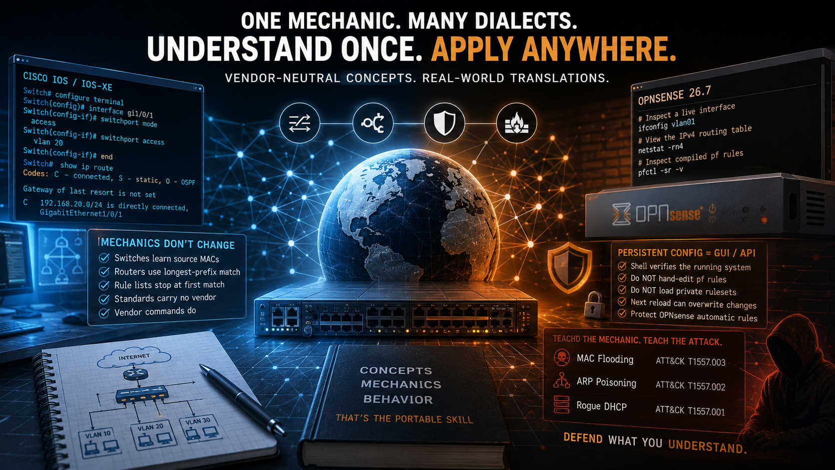
Every configuration example identifies its dialect. Cisco IOS or IOS-XE remains common in classrooms and certification material, so it carries the switching examples. OPNsense 26.7 carries the firewall and router translation where the platform has an equivalent function. The OPNsense paths and commands in this post were checked against the current official documentation in August 2026.
Syntax is the inexpensive part to relearn. The mechanics transfer: switches still learn source MAC addresses, routers still perform longest-prefix matching, and first-match rule lists still stop at the first match. Standards-based behavior carries no vendor marker. Vendor commands do.
The translation problem is smaller than it first appears:
| The job | Cisco IOS / IOS-XE | Junos | Arista EOS | OPNsense 26.7 |
|---|---|---|---|---|
| Enter or inspect an interface | interface Gi1/0/1 |
edit interfaces ge-0/0/1 |
interface Ethernet1 |
ifconfig vlan01 inspects the live interface |
| Create a VLAN | vlan 20, then name USERS |
set vlans USERS vlan-id 20 |
vlan 20, then name USERS |
Create the layer-3 VLAN device under Interfaces > Devices > VLAN; verify with ifconfig vlan01 |
| Start an ACL or filter rule | ip access-list extended WEB |
set firewall family inet filter WEB term T1 ... |
ip access-list WEB |
Add it under Firewall > Rules > interface; inspect the compiled rules with pfctl -sr -v |
| View the IPv4 routing table | show ip route |
show route |
show ip route |
netstat -rn4 |
| Preserve a configuration | copy running-config startup-config |
commit |
write memory |
Changes persist to /conf/config.xml; back up under System > Configuration > Backups |
The Junos filter entry is intentionally shown as a command shape. A complete term needs match conditions and an action. Exact command syntax also varies by platform release, so check the current documentation before using a vendor example outside the lab.
OPNsense needs a separate operating rule. The web interface or API is the source of truth for persistent configuration. The shell commands in this post verify the running system unless a command is explicitly described as changing it. Do not hand-edit the generated pf rules or load a private ruleset with pfctl -f; the next filter reload can overwrite it and may remove OPNsense's automatic rules.
The second convention is how attacks are taught.
I do not separate a network mechanic from the attack that abuses it. MAC flooding belongs beside the finite table it tries to exhaust. ARP poisoning belongs beside ARP's lack of authentication. Rogue DHCP belongs beside the first-response behavior it exploits.
Where MITRE ATT&CK has a direct technique, I include it. Where it does not, I say so instead of forcing a false mapping. ATT&CK changes over time, so technique references are verified again before publication.
The packet walk: every decision in order
Everything in both parts hangs from one picture.
A host in VLAN 10, 10.0.10.21, sends traffic to a server in VLAN 20, 10.0.20.10. An access switch, an 802.1Q trunk, and a router sit between them.
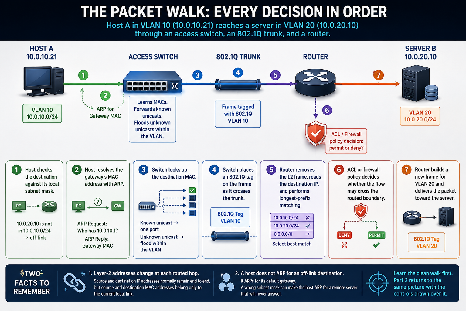
10.0.10.21 reaches a server at 10.0.20.10 through an access switch, an 802.1Q trunk, and a router. Seven decision points mark the path.Diagram showing a host, access switch, trunk, router, and server. Seven numbered decisions follow traffic from the host in VLAN 10 to the server in VLAN 20.
The walk is:
- The host compares the destination with its local subnet mask.
- The destination is off-link, so the host resolves the gateway's MAC address with ARP.
- The switch looks up the destination MAC. It forwards a known unicast to one port and floods an unknown unicast within the VLAN.
- The switch places an 802.1Q VLAN 10 tag on the frame as it crosses the trunk.
- The router removes the incoming layer-2 frame, reads the destination IP address, and performs longest-prefix matching against its routing table.
- An ACL or firewall policy decides whether the flow may cross the routed boundary.
- The router builds a new frame for VLAN 20 and delivers the packet toward the server.
Every decision before delivery is a place where configuration, failure, or enforcement can affect the flow.
Two facts from this walk will keep paying you back.
First, layer-2 addresses change at each routed hop. Source and destination IP addresses normally remain end to end, but source and destination MAC addresses belong only to the current local link. This is one of the most useful facts when reading a packet capture.
Second, a host does not ARP for an off-link destination. It ARPs for its default gateway. A wrong subnet mask can make the host ARP for a remote server that will never answer, which looks like a dead server until you inspect the local addressing decision.
Learn the clean walk first. Part 2 returns to the same picture with the controls drawn over it.
The network under the security
The layered model is a troubleshooting vocabulary
The OSI model earns its keep as a shared language for fault isolation. It is not a perfect diagram of modern protocol implementation.
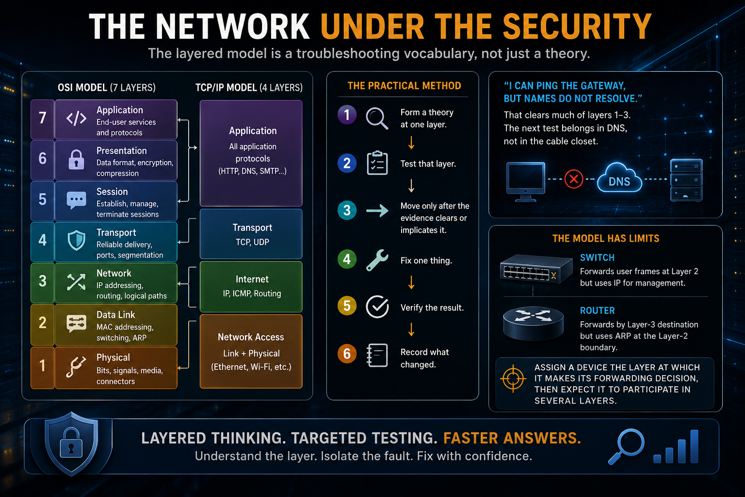
Layers 5 and 6 describe functions that exist, but TCP/IP usually folds them into the application layer. Teach seven layers for the exam. Use the four-layer TCP/IP model when reading real protocol stacks and captures.
The practical method is simple:
- Form a theory at one layer.
- Test that layer.
- Move only after the evidence clears or implicates it.
- Fix one thing.
- Verify the result.
- Record what changed.
"I can ping the gateway, but names do not resolve" clears much of layers 1 through 3. The next test belongs in DNS, not in the cable closet.
The model also has limits. A switch forwards user frames at layer 2 but uses IP for management. A router forwards by layer-3 destination while using ARP at the layer-2 boundary. Assign a device the layer at which it makes its forwarding decision, then expect it to participate in several layers.
TCP repairs, UDP races, and ports identify the application
TCP is an ordered byte stream. Networks still lose packets. TCP earns its reliability by detecting loss and repairing it through sequence numbers, acknowledgments, retransmission, flow control, and congestion control.
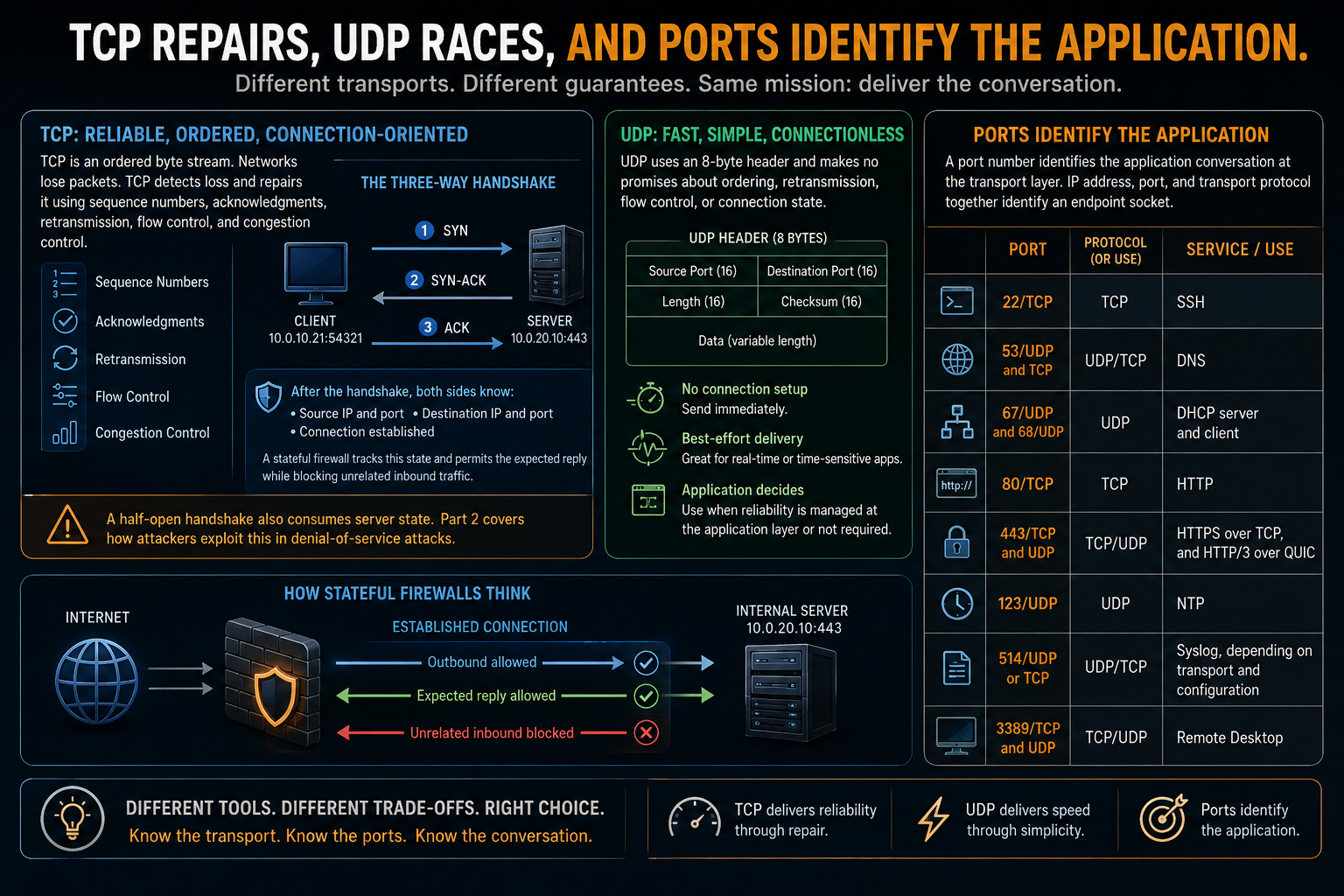
The three-way handshake is:
SYN
SYN-ACK
ACK
After those exchanges, an observer knows both IP addresses, both ports, and that the connection was established. A stateful firewall keeps the same basic conversation state, which is why it can permit the expected reply while blocking unrelated inbound traffic.
A half-open handshake also consumes server state. Part 2 returns to that fact when it covers denial of service.
UDP carries an 8-byte header and makes no promises about ordering, retransmission, flow control, or connection state. It is appropriate when a repair would arrive too late to help, as with real-time voice, or when the application can manage reliability itself. It also fits small request-and-response protocols where a TCP handshake would add unnecessary cost.
A port number identifies the application conversation at the transport layer. IP address, port, and transport protocol together identify an endpoint socket.
The ports used throughout this pair include:
| Port | Protocol or use |
|---|---|
| 22/TCP | SSH |
| 53/UDP and TCP | DNS |
| 67/UDP and 68/UDP | DHCP server and client |
| 80/TCP | HTTP |
| 443/TCP and UDP | HTTPS over TCP, and HTTP/3 over QUIC |
| 123/UDP | NTP |
| 514/UDP or TCP | Syslog, depending on transport and configuration |
| 3389/TCP and UDP | Remote Desktop |
You will meet every one again.
ARP finds local neighbors
ARP answers one question: I know an IPv4 address on my local link, but which MAC address owns it?
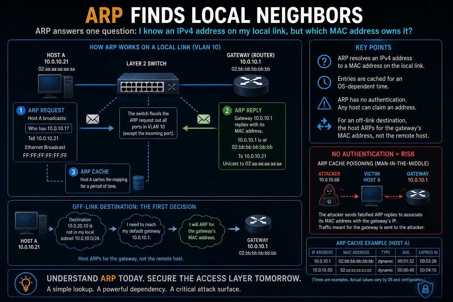
The requester broadcasts:
Who has 10.0.10.1?
The owner replies with its MAC address, and the requester caches the answer for an operating-system-dependent period.
ARP has no authentication. Any local host can claim an address, which creates the opening for ARP cache poisoning. Hold that fact until the access-layer controls appear.
For an off-link destination, the host resolves the gateway's MAC address rather than the remote host's MAC address. That is the first decision in the packet walk.
ICMP reports network conditions
ICMP is part of the network's control and error-reporting system.
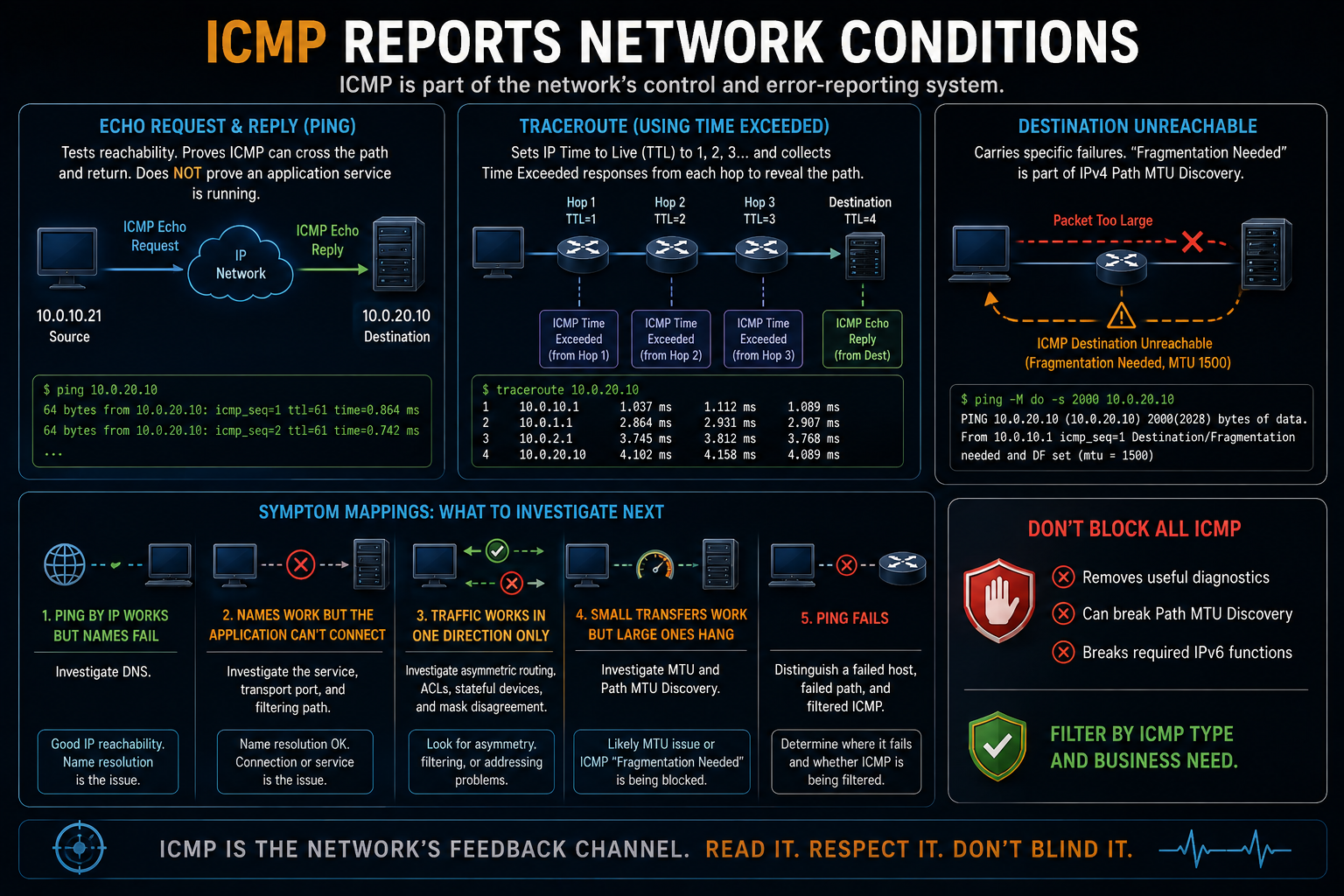
Echo Request and Echo Reply support ping. They answer whether ICMP can cross the layer-3 path and return. They do not prove that an application service is running.
Traceroute sets the IP Time to Live to 1, then 2, then 3, and collects Time Exceeded responses from each routed hop. It uses expiration deliberately to reveal the path.
Destination Unreachable messages carry more specific failures. The fragmentation-needed message is part of IPv4 Path MTU Discovery. Blocking it can produce a familiar symptom: small exchanges work, but larger transfers hang.
"Block all ICMP" is not a serious policy. It removes useful diagnostics, can break Path MTU Discovery, and breaks required IPv6 functions. Filter by ICMP type and business need rather than discarding the whole protocol.
Keep these symptom mappings:
- Ping by IP works but names fail: investigate DNS.
- Name resolution works but the application cannot connect: investigate the service, transport port, and filtering path.
- Traffic works in one direction only: investigate asymmetric routing, ACLs, stateful devices, and mask disagreement.
- Small transfers work but large ones hang: investigate MTU and Path MTU Discovery.
- Ping fails: distinguish a failed host, failed path, and filtered ICMP.
Read a prefix as fluently as a word
A subnet mask divides an address into network and host bits. A host compares its own network with the destination network to decide whether to send directly or through the gateway.
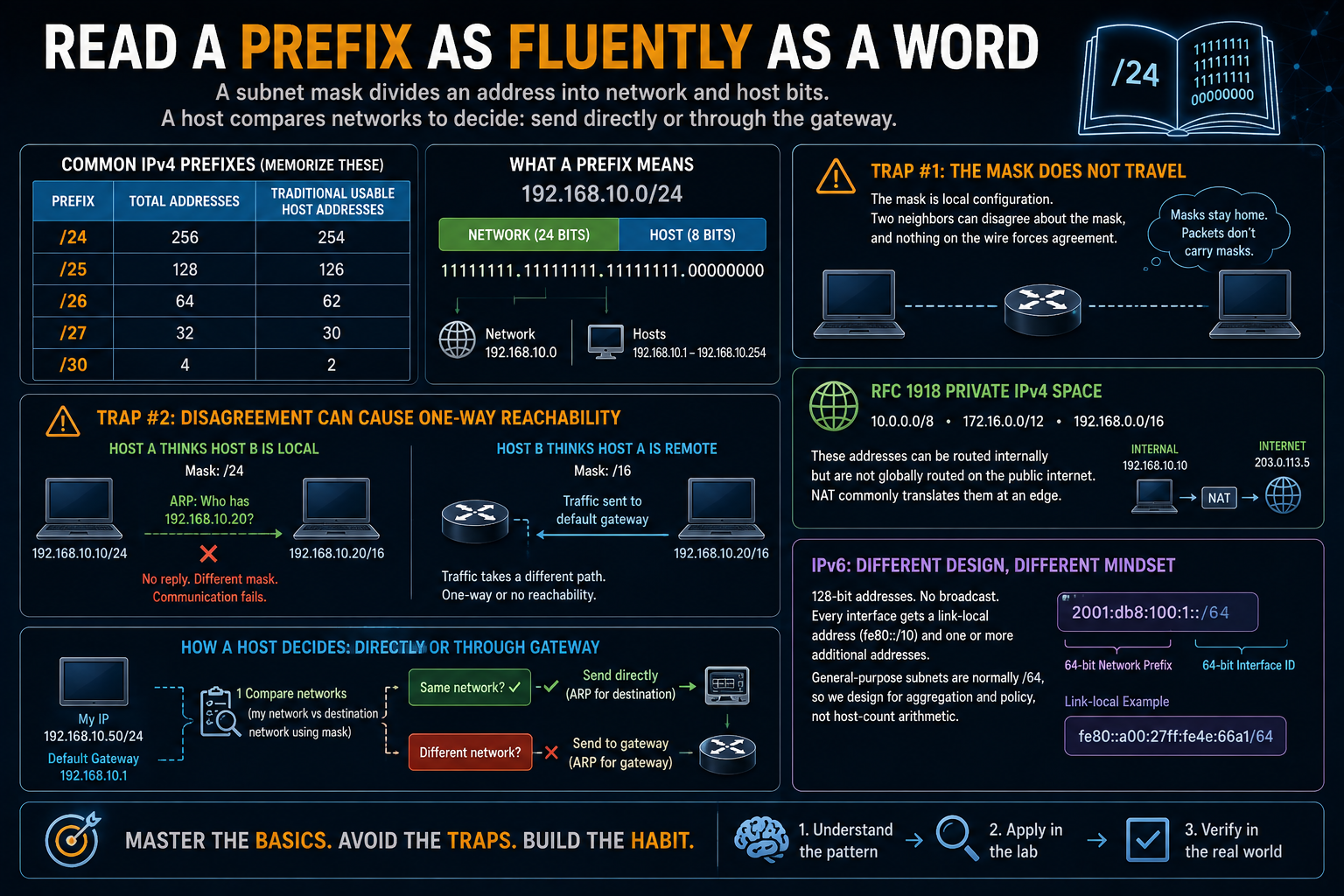
The first fluency goal is reading common IPv4 prefixes without calculating them every time:
| Prefix | Total addresses | Traditional usable host addresses |
|---|---|---|
/24 |
256 | 254 |
/25 |
128 | 126 |
/26 |
64 | 62 |
/27 |
32 | 30 |
/30 |
4 | 2 |
Two traps matter.
The mask does not travel inside each IPv4 packet. It is local configuration. Two neighbors can disagree about the mask, and nothing on the wire forces agreement.
That disagreement can cause one-way reachability. One host treats the other as local and ARPs for it. The other treats the first as remote and sends through a gateway.
RFC 1918 private IPv4 space includes 10.0.0.0/8, 172.16.0.0/12, and 192.168.0.0/16. Those addresses can be routed internally but are not globally routed on the public internet. NAT commonly translates them at an edge.
IPv6 uses 128-bit addresses, has no broadcast, and normally gives every interface a link-local fe80::/10 address plus one or more additional addresses. General-purpose IPv6 subnets are normally /64, so the design effort moves away from host-count arithmetic and toward aggregation and policy.
One /24, divided deliberately
The following plan divides 10.0.20.0/24 into functional segments:
| Segment | Need | Allocation | Host range | Gateway |
|---|---|---|---|---|
| Users, VLAN 10 | About 100 | 10.0.20.0/25 |
.1 through .126 |
10.0.20.1 |
| Servers, VLAN 20 | About 40 | 10.0.20.128/26 |
.129 through .190 |
10.0.20.129 |
| Management, VLAN 99 | About 20 | 10.0.20.192/27 |
.193 through .222 |
10.0.20.193 |
| Reserved | Growth | 10.0.20.224/27 |
Documented reserve | None |
The arithmetic needs one explanation.
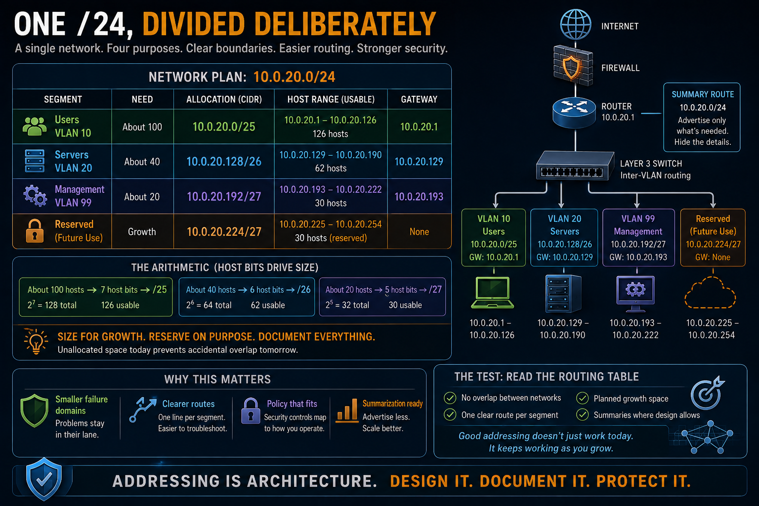
/24, divided deliberatelyAbout 100 hosts require 7 host bits, which gives a /25. About 40 require 6 host bits, which gives a /26. About 20 require 5 host bits, which gives a /27.
Size for expected growth rather than today's exact count. Reserve the remainder on purpose and document it before someone allocates it by accident.
The functional segments already resemble security zones. That is intentional. An addressing plan becomes easier to route, summarize, and protect when it follows operational boundaries.
Subnetting private space is not mainly about conserving addresses. The more important products are smaller failure domains, clearer routes, and places where policy can apply.
The test of an addressing plan is the routing table it produces: no overlap, one clear line per segment, planned growth, and summaries where the design allows them.
Topology and device roles
Most field topology reduces to a few forms.
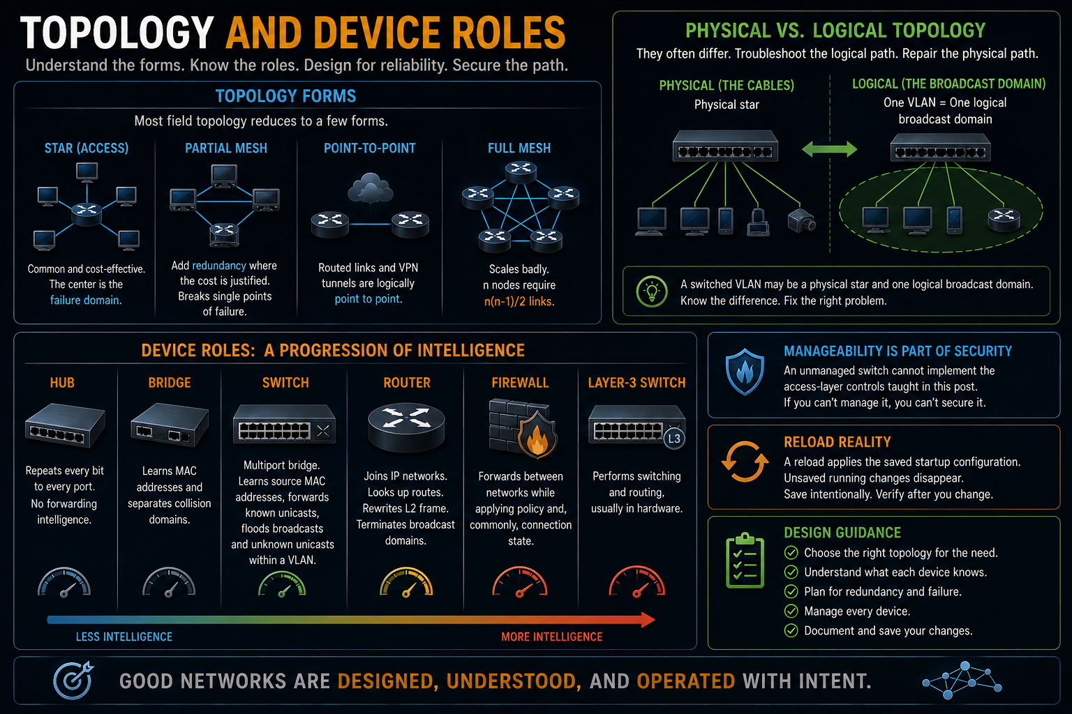
An access layer is usually a star. The center is the failure domain. A partial mesh adds redundancy where the cost is justified. Routed links and VPN tunnels are logically point to point. Full mesh scales badly because n nodes require n(n-1)/2 links.
Physical and logical topology often differ. A switched VLAN may be a physical star and one logical broadcast domain. Troubleshoot the logical path. Repair the physical path.
Device roles form a progression based on what each device knows:
- A hub repeats every bit to every port. It has no forwarding intelligence.
- A bridge learns MAC addresses and separates collision domains.
- A switch is a multiport bridge. It learns source MAC addresses, forwards known unicasts, and floods broadcasts and unknown unicasts within a VLAN.
- A router joins IP networks. It examines destination IP addresses, performs a route lookup, rewrites the layer-2 frame, and terminates broadcast domains.
- A firewall forwards between networks while applying policy and, commonly, connection state.
- A layer-3 switch performs switching and routing, usually in hardware.
An unmanaged switch cannot implement the access-layer controls taught in this post. Manageability is part of the security requirement.
Cabling, connectors, racks, and NIC hardware belong in other material. One operational fact belongs here: a reload applies the saved startup configuration. Unsaved running changes disappear.
First exercises: the network mechanics
Use Cisco Packet Tracer, GNS3, EVE-NG Community, or containerlab with images you are licensed to run. Product terms and image rights change, so check them before downloading lab software.
Complete three exercises tonight.
Exercise 1: subnet three networks on paper
Take 172.16.40.0/24 and allocate space for:
- About 110 users
- About 25 printers
- About 12 management devices
- A documented reserve
Use the same method as the worked plan, but calculate your own boundaries.
Exercise 2: speak the packet walk
Walk from ARP-for-the-gateway through delivery without notes. Say what address each device reads and what it changes.
Where you stop is the first subject to review.
Exercise 3: build the prompt
Create a lab with two switches and one router. Reach the CLI on every device. Save the initial configuration and prove that it survives a reload.
The rest of this pair runs in that lab.
Switching and the access layer
A switch is a table that teaches itself
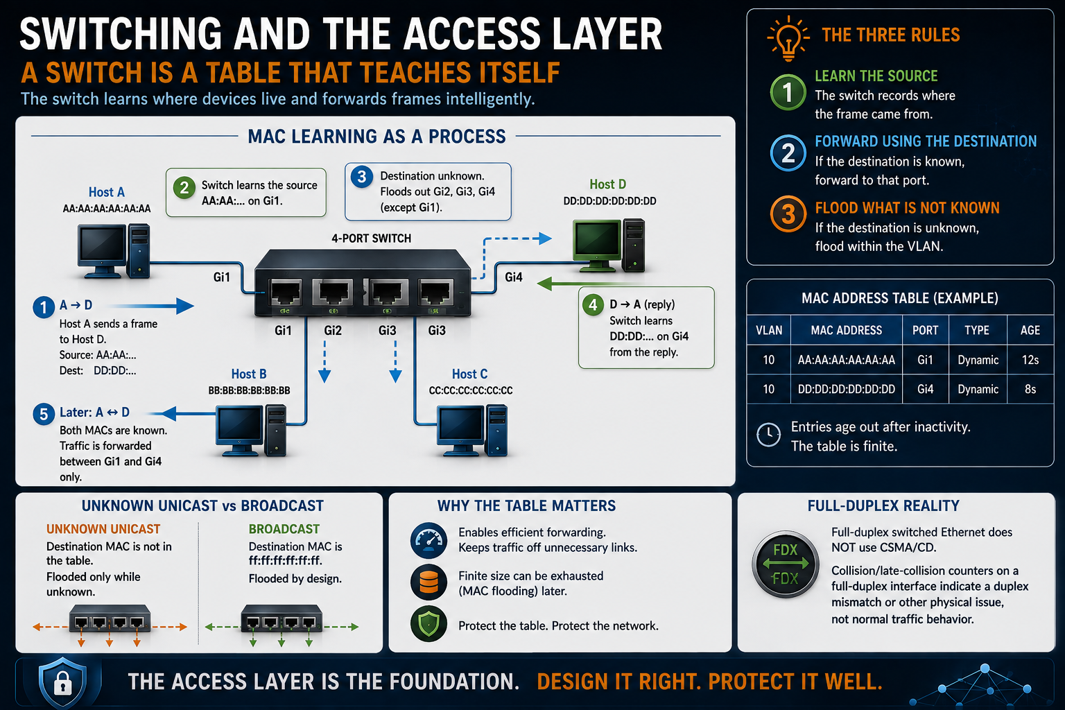
Gi1, floods the unknown destination, then learns D on Gi4 from the reply. Later traffic follows the learned ports.A four-port switch connected to hosts A through D. A MAC address table and numbered arrows show source learning, unknown-unicast flooding, reply learning, and later forwarding.
Watch one frame and the switch explains itself.
Host A sends to Host D. The switch reads the source MAC address and learns that A is reachable through Gi1. D is not yet in the table, so the switch floods a copy out every eligible port in the VLAN except the ingress port.
D replies. The switch learns D on Gi4. Future traffic between A and D can be forwarded to the known ports.
Remember three behaviors:
- Learn the source.
- Forward using the destination.
- Flood what is not known.
The learned table is commonly called the MAC address table or CAM table. It is finite, which matters when MAC flooding appears later.
Do not confuse an unknown unicast with a broadcast. A broadcast uses destination ff:ff:ff:ff:ff:ff and is flooded by design. An unknown unicast is flooded only while the destination is missing from the table.
Full-duplex switched Ethernet does not use CSMA/CD. Collision or late-collision counters on a full-duplex interface point toward a duplex mismatch or another physical problem. They are not normal traffic behavior.
A VLAN is a broadcast domain chosen on purpose
Without VLAN separation, switch ports share one broadcast domain. ARP, DHCP broadcasts, unknown-unicast flooding, and layer-2 faults can reach the whole domain.
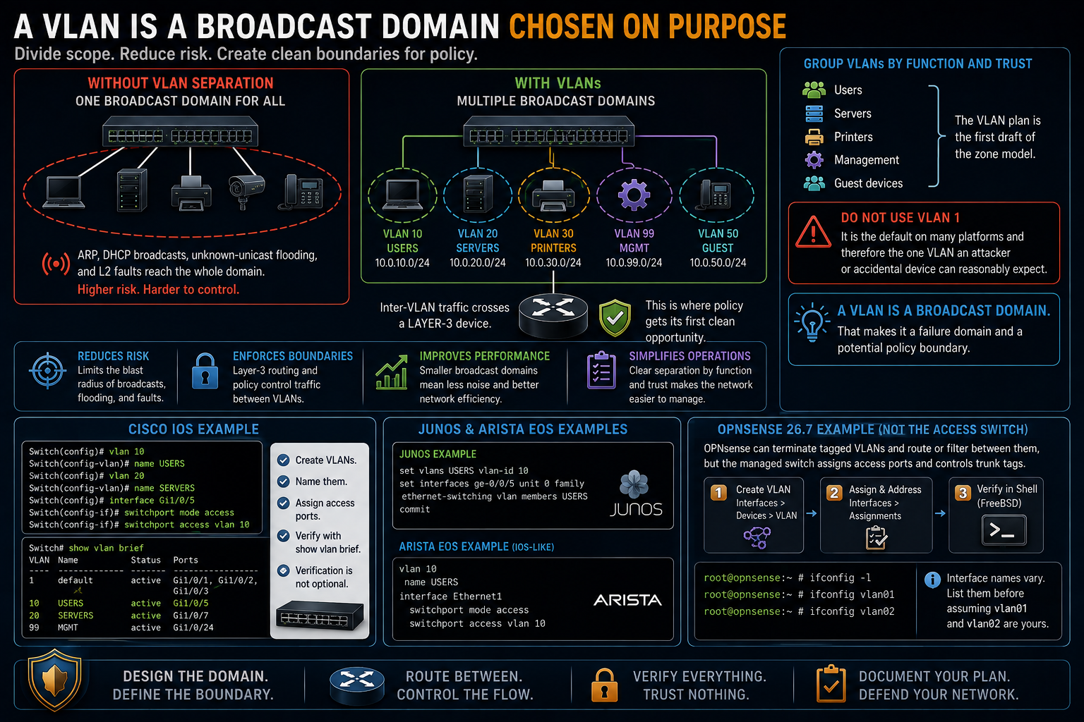
VLANs divide that scope through configuration. Each VLAN has its own layer-2 forwarding domain, normally its own IP subnet, and a corresponding route when it must communicate with another network.
Inter-VLAN traffic crosses a layer-3 device. That routed boundary is where policy gets its first clean opportunity.
Group VLANs by function and trust rather than by floor number alone:
- Users
- Servers
- Printers
- Management
- Guest devices
The VLAN plan is the first draft of the zone model.
Do not use VLAN 1 for deliberate endpoint placement. It is the default on many platforms and therefore the one VLAN an attacker or accidental device can reasonably expect.
[Cisco IOS shown]
Switch(config)# vlan 10
Switch(config-vlan)# name USERS
Switch(config)# vlan 20
Switch(config-vlan)# name SERVERS
Switch(config)# interface Gi1/0/5
Switch(config-if)# switchport mode access
Switch(config-if)# switchport access vlan 10

Switch# show vlan brief
VLAN Name      Status    Ports
10   USERS     active    Gi1/0/5
20   SERVERS   active    Gi1/0/7
On Junos, create the VLAN with set vlans USERS vlan-id 10 and assign it under the interface's Ethernet-switching family. Arista EOS follows an IOS-like command structure.
OPNsense is not the access switch in this example. It can terminate tagged VLANs and route or filter between them, but the managed switch still assigns access ports and controls which tags cross the trunk. Create the VLAN devices under Interfaces > Devices > VLAN, assign and address them under Interfaces > Assignments, then verify the live FreeBSD interfaces from an OPNsense shell. The generated device names vary, so list them before assuming that vlan01 and vlan02 are yours.
[OPNsense 26.7 shell shown]
root@opnsense:~ # ifconfig -l
root@opnsense:~ # ifconfig vlan01
root@opnsense:~ # ifconfig vlan02
show vlan brief is not decoration. Verification belongs in the command sequence.
A VLAN is a broadcast domain. That makes it a failure domain and a potential policy boundary.
802.1Q trunks carry several VLANs
A trunk carries frames for multiple VLANs between switches or between a switch and a router. An 802.1Q tag identifies the VLAN as the frame crosses the trunk.
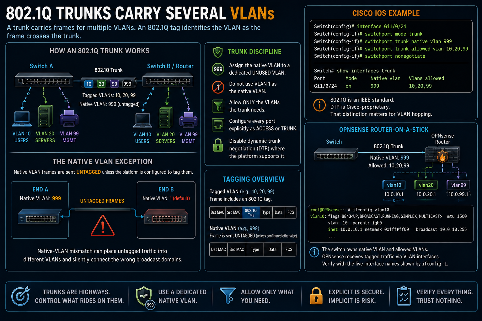
The native VLAN is the exception. Native-VLAN frames are untagged unless the platform is configured to tag them. A native-VLAN mismatch can place untagged traffic into different VLANs at each end and silently connect the wrong broadcast domains.
Use the following trunk discipline:
- Assign the native VLAN to a dedicated unused VLAN.
- Do not use VLAN 1 as the native VLAN.
- Allow only the VLANs the trunk needs.
- Configure every port explicitly as access or trunk.
- Disable dynamic trunk negotiation where the platform supports it.
[Cisco IOS shown]
Switch(config)# interface Gi1/0/24
Switch(config-if)# switchport mode trunk
Switch(config-if)# switchport trunk native vlan 999
Switch(config-if)# switchport trunk allowed vlan 10,20,99
Switch(config-if)# switchport nonegotiate

Switch# show interfaces trunk
Port     Mode   Native vlan  Vlans allowed
Gi1/0/24 on     999          10,20,99
The 802.1Q tag is standardized. Dynamic Trunking Protocol, which Cisco devices can use to negotiate trunks, is Cisco-specific. That distinction matters when we reach VLAN hopping.
On an OPNsense router-on-a-stick link, the switch owns native-VLAN handling and the allowed-VLAN list. OPNsense receives the tagged traffic through the VLAN devices attached to the parent interface. ifconfig vlan01 shows the tag and parent of the live interface; it does not replace trunk configuration on the switch.
Spanning tree disables one path to preserve the network
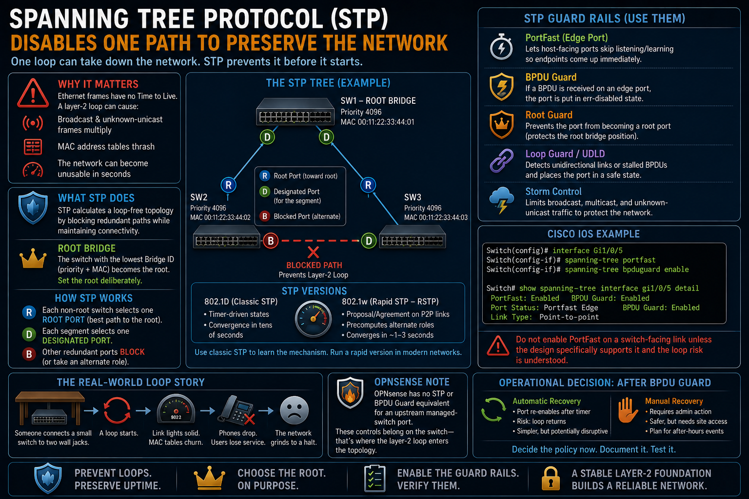
Three switches form a triangle. One is the root bridge. Root and designated ports forward, while one redundant port blocks to prevent a layer-2 loop.
Ethernet frames have no Time to Live. A layer-2 loop does not expire naturally. Broadcast and unknown-unicast frames can multiply, MAC address tables can thrash, and the network can become unusable within seconds.
Spanning Tree Protocol prevents that by calculating a loop-free topology and blocking redundant paths.
The switch with the lowest bridge ID becomes the root. The bridge ID includes priority and a MAC-based value. If all priorities remain at their defaults, the lowest bridge identifier wins for reasons unrelated to your intended traffic path.
Set the root deliberately.
Each non-root switch selects one root port, its best path toward the root. Each segment selects one designated port. Other redundant ports block or take an alternate role, depending on the spanning-tree version.
Classic 802.1D uses timer-driven states and can take tens of seconds to reconverge. Rapid Spanning Tree, 802.1w, uses proposal and agreement behavior on supported point-to-point links and precomputes alternate roles, producing much faster recovery in a correctly designed topology.
Use classic STP to learn the mechanism. Run a rapid version in modern networks.
The failure story is familiar. Someone places a small switch under a conference table and connects two of its ports to wall jacks. The loop starts. Link lights turn solid, MAC tables churn, phones drop, and users lose service.
The guard rails are:
- PortFast or edge-port behavior on host-facing ports, so endpoints do not wait through spanning-tree transitions
- BPDU guard on those same edge ports, so a received BPDU disables the port
- Root guard on ports facing devices that must never become the root
- Loop guard or unidirectional-link protection on appropriate switch links
- Storm control as a per-port circuit breaker for excessive broadcast, multicast, or unknown-unicast traffic
[Cisco IOS shown]
Switch(config-if)# spanning-tree portfast
Switch(config-if)# spanning-tree bpduguard enable
Do not enable PortFast on a switch-facing link unless the design specifically supports that behavior and the loop risk is understood.
OPNsense has no STP or BPDU-guard equivalent for an upstream managed-switch port. Those controls belong on the switch because that is where the layer-2 loop enters the topology.
Decide what happens after BPDU guard disables a port. Automatic recovery can reconnect the loop every few minutes. Manual recovery can require an after-hours site visit. That is an operational decision for change review, not for improvisation during an outage.
Link aggregation and PoE
LACP, standardized through 802.1AX, combines parallel physical links into one logical link. Spanning tree sees the bundle as one interface, so the links can provide aggregate capacity and redundancy without being blocked individually.
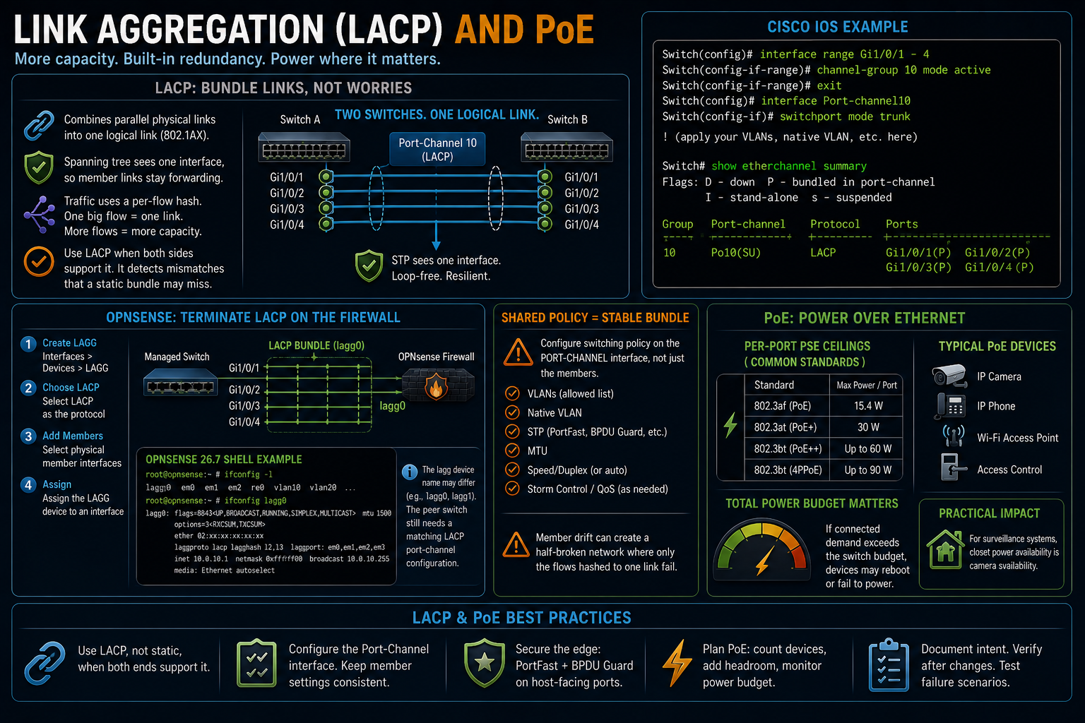
Traffic distribution is normally based on a per-flow hash. One large flow still uses one member link. The bundle increases total capacity across multiple flows rather than making one flow as fast as the sum of every member.
Use LACP instead of a static bundle when both platforms support it. LACP can detect several mismatches that a forced static bundle may forward into.
[Cisco IOS shown]
Switch(config-if-range)# channel-group 10 mode active
OPNsense can terminate an LACP bundle on the firewall side. Create it under Interfaces > Devices > LAGG, choose LACP, add the member interfaces, then assign the resulting device. Verify the running aggregate from the shell:
[OPNsense 26.7 shell shown]
root@opnsense:~ # ifconfig -l
root@opnsense:~ # ifconfig lagg0
The actual lagg device name may differ. The peer switch still needs a matching LACP port-channel configuration.
Configure shared switching policy on the port-channel interface. Member drift can produce a half-broken network where only the flows hashed to one link fail.
Power over Ethernet supplies power through the data cable. Common per-port PSE ceilings are 15.4 W for 802.3af, 30 W for 802.3at, and up to 60 W or 90 W for 802.3bt classes.
The switch also has a total power budget. If the connected demand exceeds that budget, cameras, phones, or access points may reboot or fail to power. For surveillance systems, closet power availability is part of camera availability.
Attack and control pairings at the access layer
MAC flooding targets the finite forwarding table
A switch learns source MAC addresses into a finite table. An attacker can generate frames with many invented source addresses in an attempt to consume that capacity.
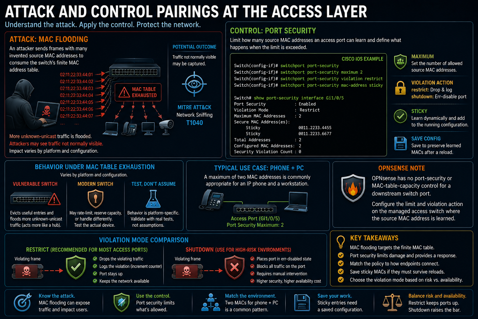
Behavior under exhaustion varies by platform and configuration. A vulnerable switch may evict useful entries and flood more unknown-unicast traffic, making traffic visible on ports where it normally would not appear. Modern platforms may also rate-limit, protect reserved capacity, or respond differently. Test the actual device rather than assuming every switch becomes a perfect hub.
MITRE ATT&CK has no dedicated MAC-flooding technique. If the attack produces packet capture from traffic not normally visible to the host, the outcome can support Network Sniffing, T1040.
Port security constrains how many source MAC addresses an access port may learn and defines the violation response.
[Cisco IOS shown]
Switch(config-if)# switchport port-security
Switch(config-if)# switchport port-security maximum 2
Switch(config-if)# switchport port-security violation restrict
Switch(config-if)# switchport port-security mac-address sticky

Switch# show port-security interface Gi1/0/5
Port Security : Enabled
Violation Mode : Restrict
OPNsense has no port-security or MAC-table-capacity control for a downstream switch port. Configure the limit and violation action on the managed access switch where the source MAC address is learned.
A maximum of two may be appropriate when an IP phone and a workstation share one physical access port. The policy has to match the endpoint arrangement.
Sticky learning adds dynamically learned secure MAC addresses to the running configuration on supported IOS platforms. Save the configuration if those learned entries must survive a reload.
restrict drops violating traffic and records the violation without disabling the entire port. shutdown places the port into an error-disabled state. Choose the mode based on the expected risk and the availability cost.
VLAN hopping abuses trunk behavior
VLAN hopping has two commonly taught forms.
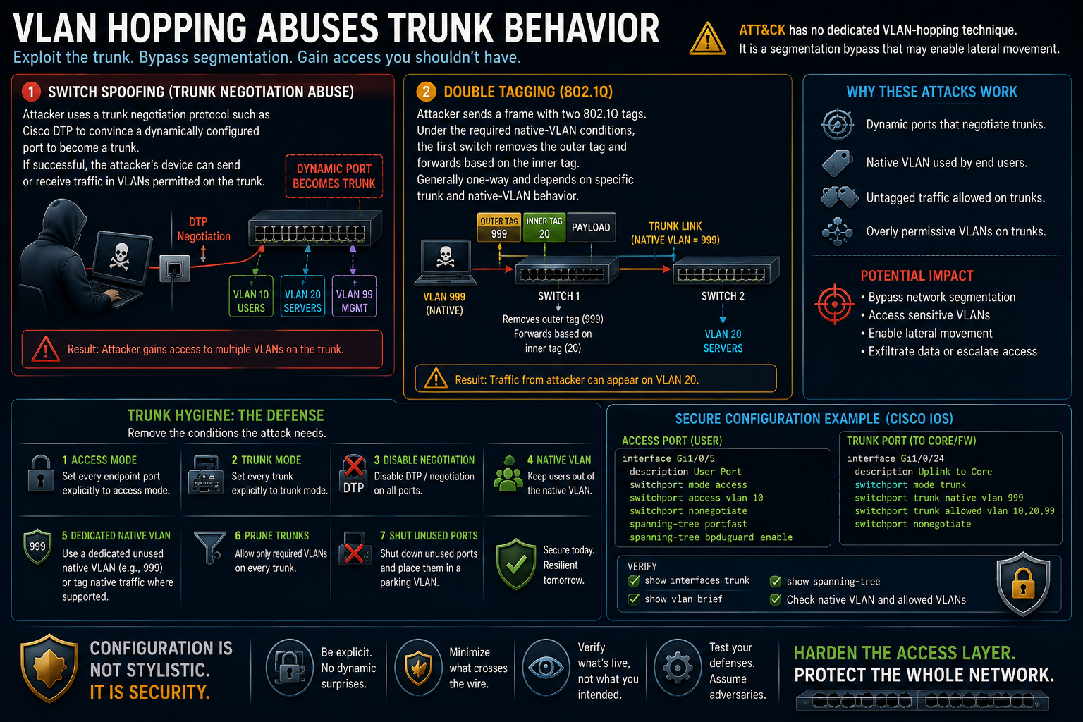
Switch spoofing uses a trunk-negotiation protocol such as Cisco DTP to convince a dynamically configured port to become a trunk. If successful, the attacker's device can send or receive traffic in VLANs permitted on that trunk.
Double tagging places two 802.1Q tags in a frame. Under the required native-VLAN conditions, the first switch removes the outer tag and forwards according to the inner tag. The attack is generally one-way and depends on specific trunk and native-VLAN behavior.
ATT&CK does not provide a dedicated VLAN-hopping technique. Describe it honestly as a segmentation bypass that may enable lateral movement rather than assigning a false identifier.
The defense is the trunk hygiene already configured:
- Set every endpoint port explicitly to access mode.
- Set every trunk explicitly to trunk mode.
- Disable negotiation.
- Keep users out of the native VLAN.
- Use a dedicated unused native VLAN or tag native traffic where supported.
- Prune every trunk to required VLANs.
- Shut down unused ports and place them in a parking VLAN.
The configuration is not stylistic. Each line removes a condition the attack needs.
ARP poisoning creates an on-path position
ARP accepts unauthenticated address claims. An attacker can tell a victim that the gateway IP belongs to the attacker's MAC address, then tell the gateway that the victim IP belongs to the attacker. If the attacker forwards traffic between them, the attacker occupies the path.
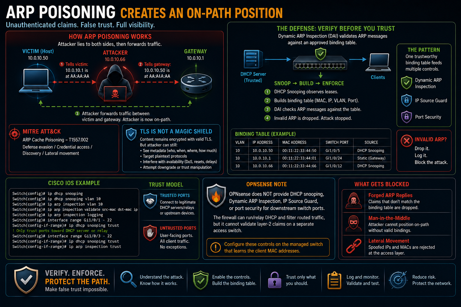
MITRE ATT&CK identifies this as ARP Cache Poisoning, T1557.002.
TLS still matters in that position, but "HTTPS makes an on-path attacker harmless" is too broad. Correct certificate validation protects encrypted application content. The attacker can still observe metadata, target plaintext protocols, interfere with availability, and attempt downgrade or trust-manipulation attacks.
Dynamic ARP Inspection checks ARP messages against an approved binding table. DHCP snooping commonly builds that table from observed DHCP assignments, associating MAC address, IP address, VLAN, and switch port.
IP Source Guard can use the same bindings to reject spoofed IPv4 source addresses.
The pattern is worth remembering: one trustworthy binding table feeds several controls.
[Cisco IOS shown]
Switch(config)# ip dhcp snooping
Switch(config)# ip dhcp snooping vlan 10
Switch(config)# ip arp inspection vlan 10
OPNsense does not provide DHCP snooping, Dynamic ARP Inspection, IP Source Guard, or port security for downstream switch ports. The firewall can run or relay DHCP and filter routed traffic, but it cannot validate layer-2 claims on a separate access switch. Configure these controls on the managed switch that learns the client MAC addresses.
Only interfaces toward the legitimate DHCP server or relay path should be trusted. User-facing ports remain untrusted.
Start the evidence thread by causing a violation
From this point forward, every control you configure should also be tested deliberately. Cause the expected failure and read what the device records.
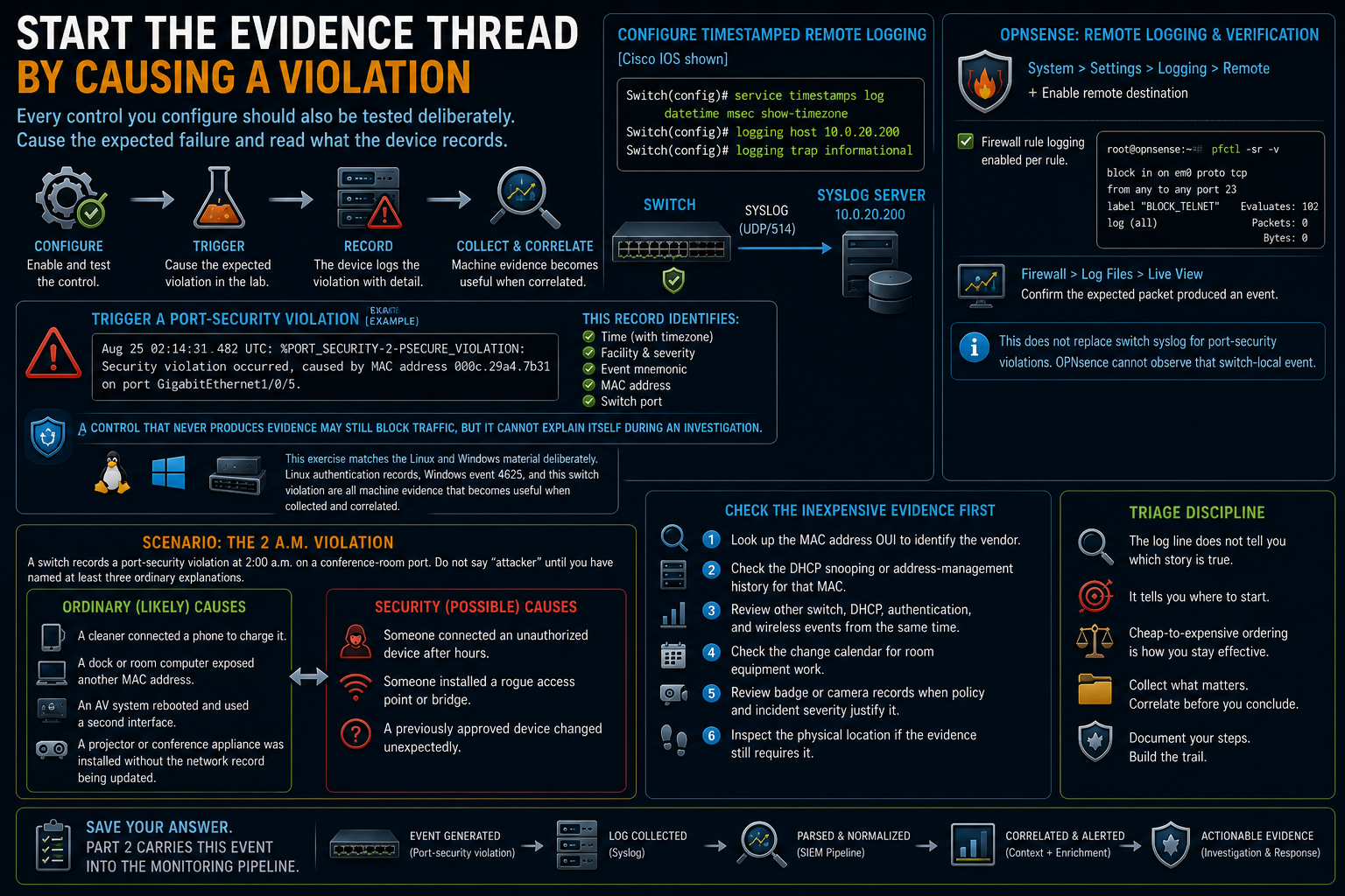
Configure timestamped remote logging:
[Cisco IOS shown]
Switch(config)# service timestamps log datetime msec show-timezone
Switch(config)# logging host 10.0.20.200
Switch(config)# logging trap informational
For OPNsense-generated events, configure the remote destination under System > Settings > Logging > Remote. Firewall-rule logging is enabled per rule. Confirm the generated filter and its counters from the shell with pfctl -sr -v, then use Firewall > Log Files > Live View to confirm that the expected packet produced an event. This does not replace switch syslog for port-security violations because OPNsense cannot observe that switch-local event.
Then trigger a port-security violation in the lab:
Aug 25 02:14:31.482 UTC: %PORT_SECURITY-2-PSECURE_VIOLATION:
Security violation occurred, caused by MAC address 000c.29a4.7b31
on port GigabitEthernet1/0/5.
The record identifies a time, facility, severity, event mnemonic, MAC address, and switch port.
A control that never produces evidence may still block traffic, but it cannot explain itself during an investigation. Detection and testimony are part of the design.
This exercise matches the Linux and Windows material deliberately. Linux authentication records, Windows event 4625, and this switch violation are all machine evidence that becomes useful when collected and correlated.
Scenario: the 2 a.m. violation
A switch records a port-security violation at 2:00 a.m. on a conference-room port. Do not say "attacker" until you have named at least three ordinary explanations.
Start with the likely causes:
- A cleaner connected a phone to charge it.
- A dock or room computer exposed another MAC address.
- An AV system rebooted and used a second interface.
- A projector or conference appliance was installed without the network record being updated.
Then consider the security explanations:
- Someone connected an unauthorized device after hours.
- Someone installed a rogue access point or bridge.
- A previously approved device changed unexpectedly.
Check the inexpensive evidence first:
- Look up the MAC address OUI to identify the vendor.
- Check the DHCP snooping or address-management history for that MAC.
- Review other switch, DHCP, authentication, and wireless events from the same time.
- Check the change calendar for room equipment work.
- Review badge or camera records when policy and incident severity justify it.
- Inspect the physical location if the evidence still requires it.
The log line does not tell you which story is true. It tells you where to start. Cheap-to-expensive ordering is triage discipline.
Save your answer. Part 2 carries this event into the monitoring pipeline.
First exercises: the access layer
Exercise 1: build two VLANs and a trunk
Place users and servers in separate VLANs across two switches. Configure the native VLAN deliberately and allow only the required VLANs on the trunk.
Without layer-3 routing, prove separation with a failed cross-VLAN ping. Save the command output.
Exercise 2: observe spanning tree
Build a redundant triangle or parallel path in the lab. Confirm which interface spanning tree blocks.
Disconnect the active path and measure convergence. If your simulator permits a controlled loop exercise, know which link you will disconnect before you start. Stop the storm quickly and observe how spanning tree restores a loop-free topology.
Exercise 3: trigger port security
Set the maximum to one secure MAC address, connect a second source, and read the resulting log event. Save the exact line to a text file.
The evidence required for these exercises is:
- The failed cross-VLAN ping
- The spanning-tree state and measured failover
- The saved port-security event
"It worked" is not evidence.
Routing and the boundaries
Read the routing table line by line
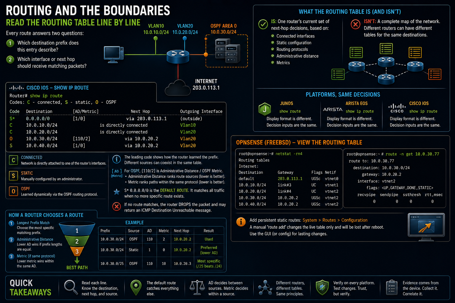
Every route answers two questions:
- Which destination prefix does this entry describe?
- Which interface or next hop should receive matching packets?
[Cisco IOS shown]
Router# show ip route
Codes: C - connected, S - static, O - OSPF

S*   0.0.0.0/0 [1/0] via 203.0.113.1
C    10.0.10.0/24 is directly connected, Vlan10
C    10.0.20.0/24 is directly connected, Vlan20
O    10.0.30.0/24 [110/2] via 10.0.20.2, Vlan20
S    10.0.40.0/24 [1/0] via 10.0.20.2
The leading code identifies how the router learned the prefix. Connected, static, and OSPF routes can coexist. Preference between route sources matters only when they offer the same prefix length for the same destination.
For the OSPF entry, [110/2] is administrative distance followed by the OSPF metric on Cisco IOS. Administrative distance ranks route sources locally. The metric ranks paths learned by the same routing protocol.
S* 0.0.0.0/0 is the default route. It matches when no more specific entry does.
If no route matches, the router drops the packet and may return an ICMP Destination Unreachable message.
A routing table is not a complete map. It is one router's current set of next-hop decisions, assembled from connected interfaces, configuration, and routing protocols. Two routers can hold different tables for the same network.
Junos uses show route. Arista EOS uses show ip route. The display format changes. The decision inputs do not.
OPNsense exposes the FreeBSD routing table from its shell. netstat -rn4 lists IPv4 routes without waiting for DNS lookups. route -n get asks which route the kernel would use for one destination.
[OPNsense 26.7 shell shown]
root@opnsense:~ # netstat -rn4
root@opnsense:~ # route -n get 10.0.30.77
Add persistent static routes under System > Routes > Configuration. A manual route add changes the live kernel table but does not make the route part of the OPNsense configuration, so it is the wrong tool for a lasting change.
Longest-prefix match decides the route
Suppose the destination is 10.0.30.77, and the router has these entries:
0.0.0.0/0
10.0.0.0/8
10.0.30.0/24
10.0.30.64/26
All four match 10.0.30.77. The /26 wins because it is the most specific.

Change the destination to 10.0.30.7. That address falls outside 10.0.30.64/26, so the /24 wins.
The selection order is:
- Longest matching prefix
- Lowest administrative distance when multiple sources offer the same prefix
- Lowest protocol metric among eligible paths from the same source
This is why a default route can coexist with every specific route. It is consulted last.
The security consequence is direct: an injected, more-specific route can attract traffic away from the intended path. Routing-protocol authentication and route filtering exist partly because a false specific route can redirect or discard traffic.
Static and dynamic routing solve different maintenance problems
Static routes are lines an administrator writes. They are predictable and silent, but they do not learn around topology changes on their own. Each affected route must be maintained as the network changes.
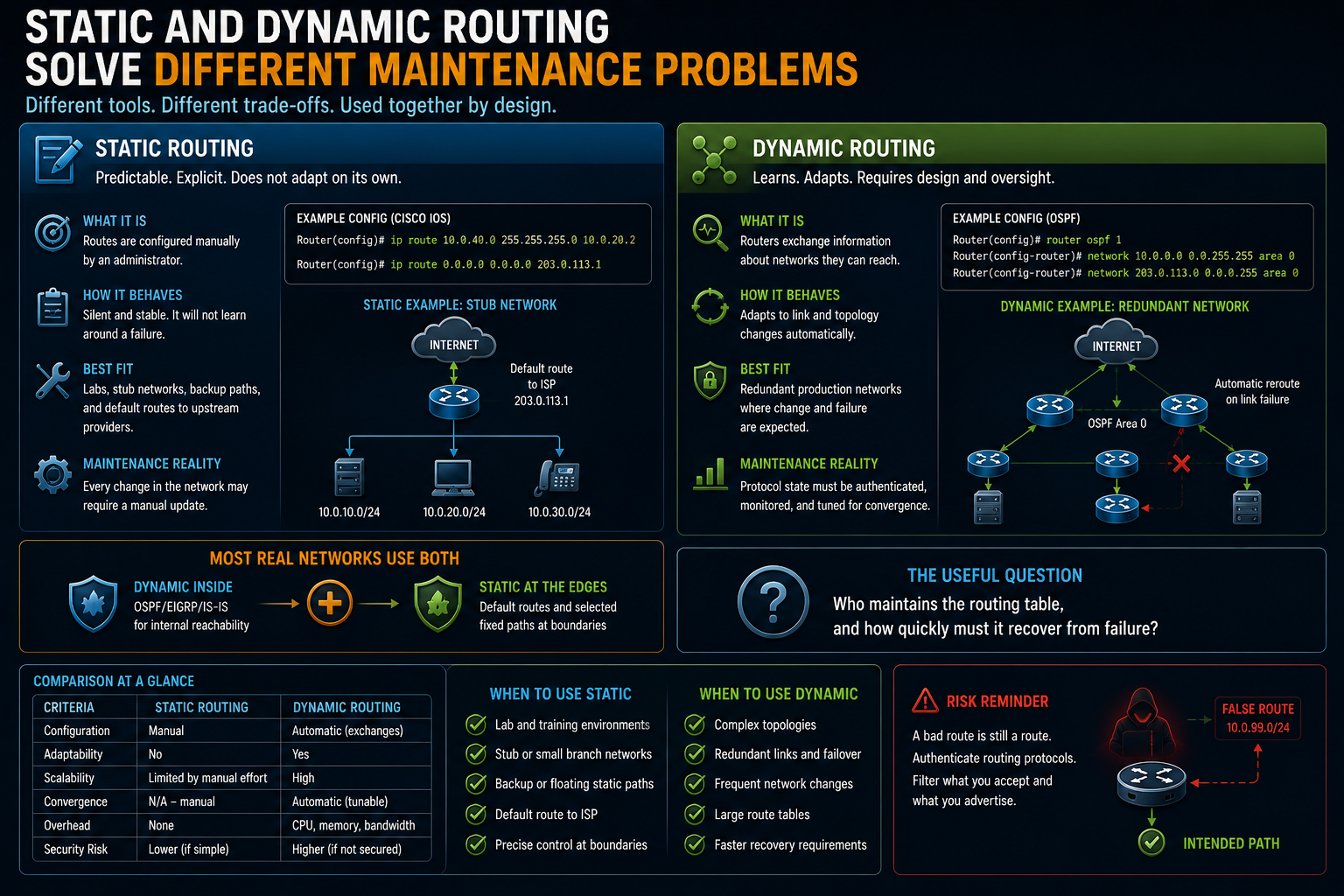
They fit labs, stub networks, deliberate backup paths, and default routes toward an upstream provider.
Dynamic routing lets routers exchange reachability information and adapt when links fail. It supports redundant production networks but creates protocol state that must be authenticated, monitored, and designed for convergence.
Most real networks use both. Dynamic routing handles internal reachability. Static defaults and selected fixed paths remain at controlled edges.
The useful question is not which one is universally better. Ask who maintains the table and how quickly it must recover from failure.
OSPF in one area
OSPF is a link-state interior routing protocol. Routers form neighbor relationships, exchange link-state information, build a shared topology database within an area, and independently calculate shortest paths.
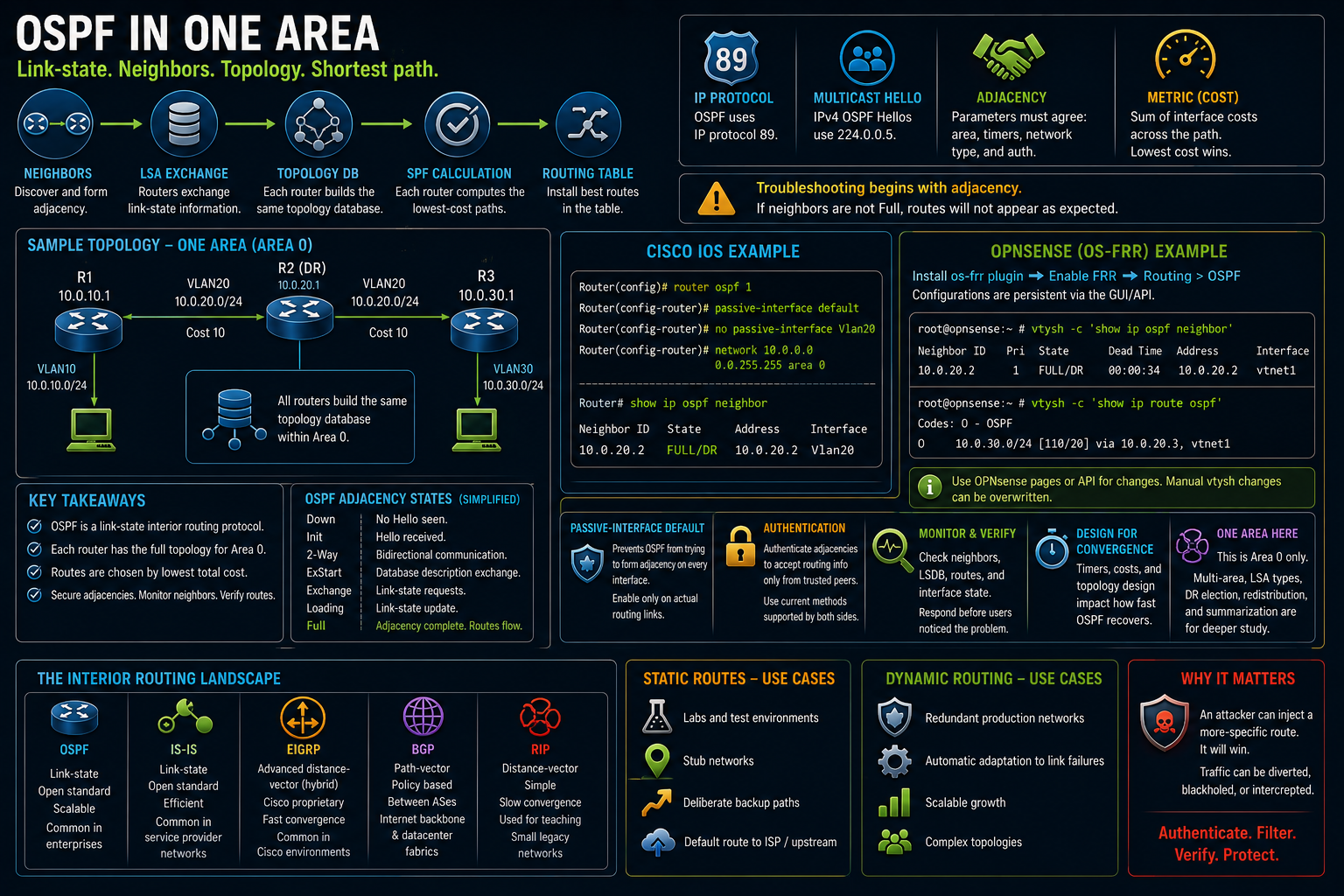
Troubleshooting begins with adjacency. If two expected neighbors are not Full, their routes will not appear as expected.
OSPF uses IP protocol 89. IPv4 OSPF routers commonly send Hello traffic to multicast 224.0.0.5. Several parameters must agree before an adjacency forms, including area, timers, network behavior, and authentication.
Cost is the route metric. The router sums interface costs across the candidate path and installs the lowest-cost result.
[Cisco IOS shown]
Router(config)# router ospf 1
Router(config-router)# passive-interface default
Router(config-router)# no passive-interface Vlan20
Router(config-router)# network 10.0.0.0 0.0.255.255 area 0

Router# show ip ospf neighbor
Neighbor ID  State    Address    Interface
10.0.20.2    FULL/DR  10.0.20.2  Vlan20
OPNsense provides dynamic routing through the os-frr plugin. Install it under System > Firmware > Plugins, enable FRR, and configure OSPF under Routing > OSPF. The plugin-backed configuration is persistent. Use FRR's vtysh for verification:
[OPNsense 26.7 with os-frr shown]
root@opnsense:~ # vtysh -c 'show ip ospf neighbor'
root@opnsense:~ # vtysh -c 'show ip route ospf'
Native FRR configuration mode is available through vtysh, but changes entered there can be replaced when OPNsense regenerates the plugin configuration. Use the OPNsense pages or API for persistent OSPF changes.
passive-interface default prevents OSPF from attempting adjacency on every enabled interface. Explicitly enable OSPF neighbor formation only on actual routing links.
Authenticate real adjacencies with a current method supported by both platforms. Legacy OSPF MD5 remains common in older examples. Modern platforms can support stronger key-chain-based authentication. Check the current platform documentation before deployment.
An unauthenticated interior routing protocol may accept routing information from an unexpected device on the segment. You already know what a more-specific route can do.
One area, area 0, is the scope here. Multi-area design, LSA types, designated-router elections, redistribution, and route summarization belong in deeper routing material.
The wider protocol map is enough for orientation:
- OSPF and IS-IS are link-state interior protocols.
- EIGRP remains common in Cisco lineages.
- BGP exchanges policy and reachability between autonomous systems and inside some datacenter fabrics.
- RIP survives mainly as a teaching protocol and in small legacy environments.
NAT is address translation, not firewall policy
| NAT type | Mapping | Typical direction | Common use |
|---|---|---|---|
| Static NAT | One private address to one public address | Fixed mapping that can support both directions | Publishing a server or maintaining a stable translation |
| Dynamic NAT | Private addresses to a public pool | Usually outbound initiated | Pool-based translation, less common now |
| PAT or overload | Many private addresses to one public address, distinguished by ports | Usually outbound initiated | User and office internet access |
PAT rewrites the source address and source port and records the mapping in a translation table. Replies use that state to return to the correct internal host.
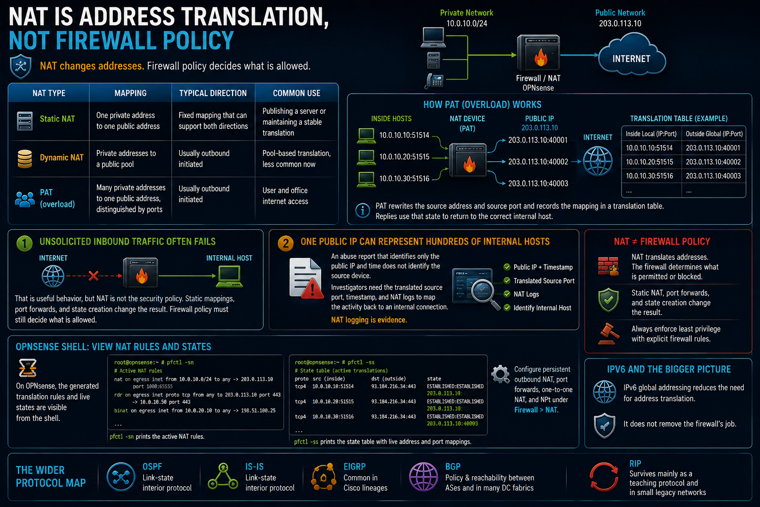
This creates two operational consequences.
First, unsolicited inbound traffic often lacks a translation and fails at the edge. That is a useful behavior, but NAT is not the security policy. Static mappings, port forwards, and state creation change the result. Firewall policy must still decide what is allowed.
Second, one public IP address can represent hundreds of internal hosts. An abuse report that identifies only the public address and time does not identify the source device. Investigators need the translated source port, timestamp, and NAT logs to map the activity back to an internal connection.
NAT logging is evidence.
On OPNsense, the generated translation rules and live states are visible from the shell:
[OPNsense 26.7 shell shown]
root@opnsense:~ # pfctl -sn
root@opnsense:~ # pfctl -ss
pfctl -sn prints the active NAT rules. pfctl -ss prints the state table, which includes the live address and port mappings. Configure persistent outbound NAT, port forwards, one-to-one NAT, and NPt under Firewall > NAT rather than by loading handwritten pf rules.
IPv6 global addressing reduces the need for address translation. It does not remove the firewall's job.
Inter-VLAN routing creates the policy chokepoint
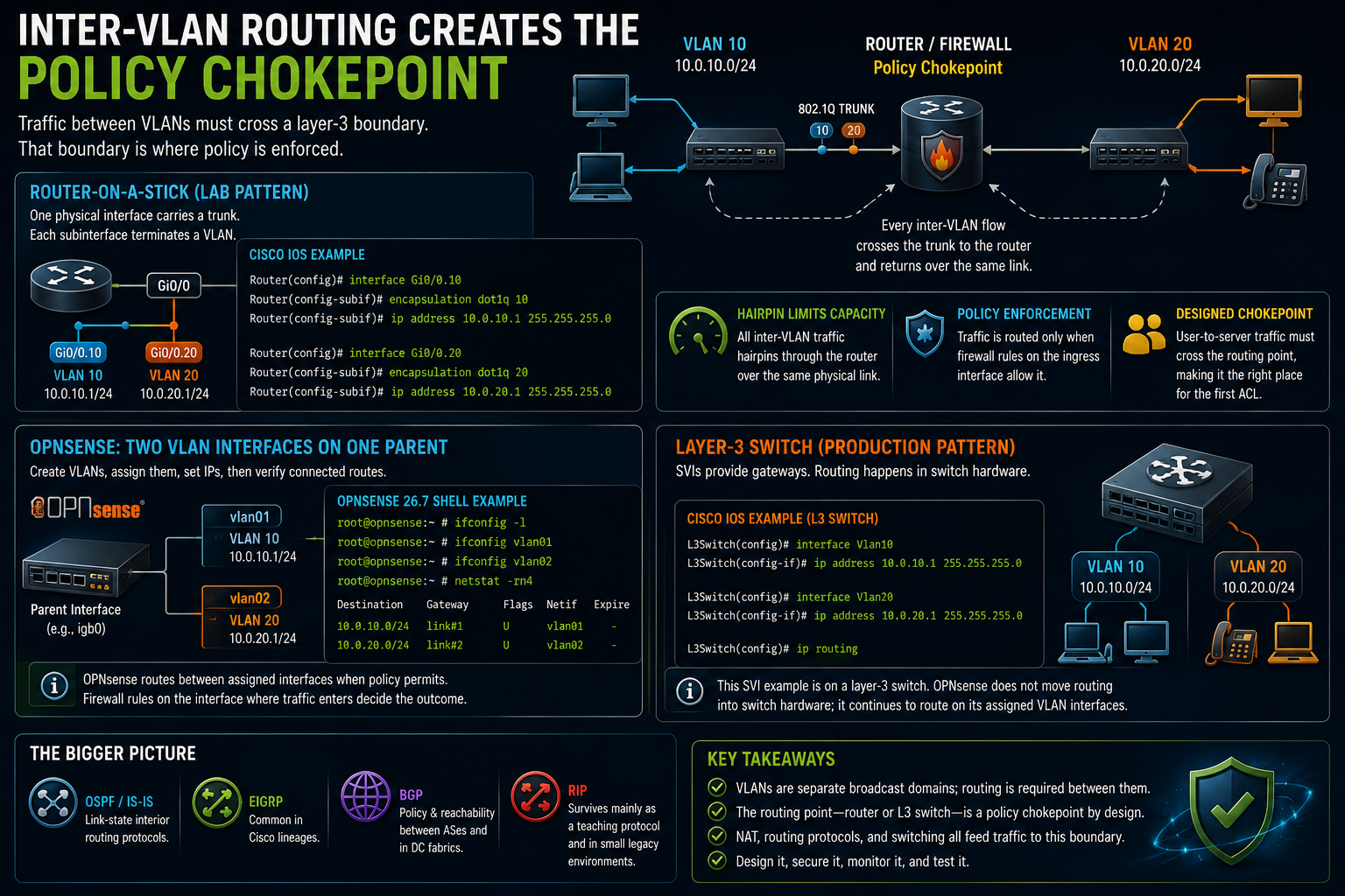
Router-on-a-stick is useful in the lab because it exposes every mechanism. One physical router interface carries a trunk, and each subinterface terminates one VLAN and provides that subnet's gateway.
[Cisco IOS shown]
Router(config)# interface Gi0/0.10
Router(config-subif)# encapsulation dot1q 10
Router(config-subif)# ip address 10.0.10.1 255.255.255.0

Router(config)# interface Gi0/0.20
Router(config-subif)# encapsulation dot1q 20
Router(config-subif)# ip address 10.0.20.1 255.255.255.0
The OPNsense form is two assigned VLAN devices on one parent interface. Create VLAN 10 and VLAN 20 under Interfaces > Devices > VLAN, assign both, enable them, and set 10.0.10.1/24 and 10.0.20.1/24 as their static IPv4 addresses. Then verify that both connected routes exist:
[OPNsense 26.7 shell shown]
root@opnsense:~ # ifconfig -l
root@opnsense:~ # ifconfig vlan01
root@opnsense:~ # ifconfig vlan02
root@opnsense:~ # netstat -rn4
OPNsense routes between assigned interfaces when policy permits the traffic. The firewall rules on the interface where traffic enters decide whether the routed flow continues.
Every inter-VLAN flow crosses the trunk to the router and returns over the same physical link. That hairpin limits capacity.
A switched virtual interface on a layer-3 switch is the production pattern in many campus networks:
[Cisco IOS shown]
L3Switch(config)# interface Vlan10
L3Switch(config-if)# ip address 10.0.10.1 255.255.255.0
L3Switch(config)# ip routing
This SVI example belongs to a layer-3 switch. OPNsense does not move that routing into switch hardware. It continues to use its assigned VLAN interfaces and enforces policy as traffic enters the firewall.
Routing occurs in the switch hardware rather than across an external router trunk. The physical implementation changes. The route lookup does not.
VLAN separation requires a layer-3 device because VLANs are distinct broadcast domains. The routing point is a chokepoint created on purpose. User-to-server traffic must cross it, which makes it the right place for the first ACL.
Zones turn trust into network geography
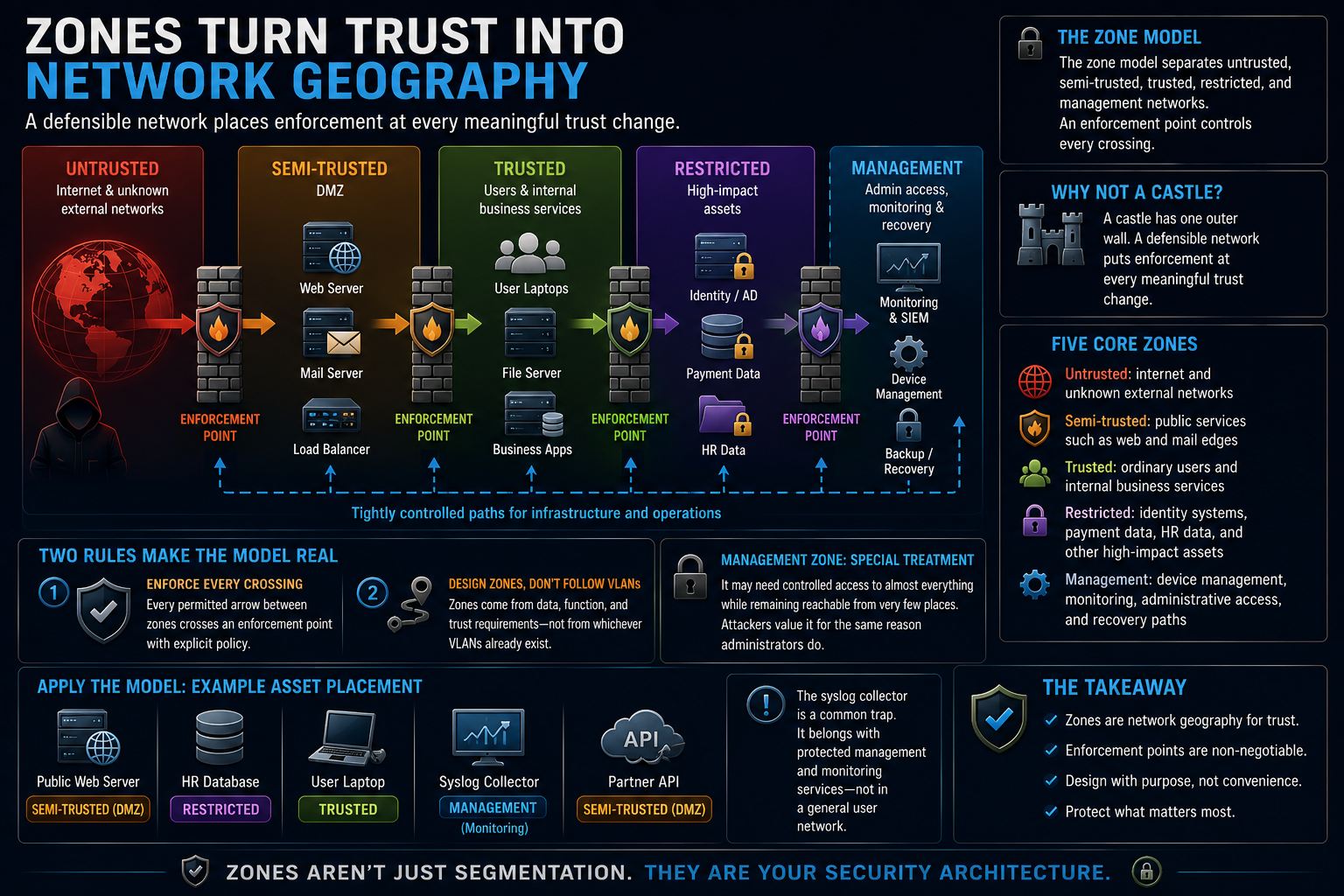
Trust zones progress from the untrusted internet through a semi-trusted DMZ and trusted internal systems to restricted assets. A separate management zone reaches infrastructure through tightly controlled paths.
The castle analogy helps only at the beginning. A castle has one outer wall. A defensible network puts enforcement at every meaningful trust change.
A simple model includes:
- Untrusted: internet and unknown external networks
- Semi-trusted: public services such as web and mail edges
- Trusted: ordinary users and internal business services
- Restricted: identity systems, payment data, HR data, and other high-impact assets
- Management: device management, monitoring, administrative access, and recovery paths
The management zone deserves separate treatment. It may need controlled access to almost everything while remaining reachable from very few places. Attackers value it for the same reason administrators do.
Two rules make the model real.
Every permitted arrow between zones crosses an enforcement point with explicit policy. Zones come from data, function, and trust requirements rather than from whichever VLANs already exist.
Place a public web server, HR database, user laptop, syslog collector, and partner API into zones and defend each choice. The syslog collector is the common trap. It belongs with protected management and monitoring services, not in a general user network.
The Handbook develops zone design from data classification, enforcement selection, and control mapping.
Firewalls belong where trust changes
A firewall evaluates traffic where zones meet. Correct rules on a badly placed firewall still produce a bad architecture.
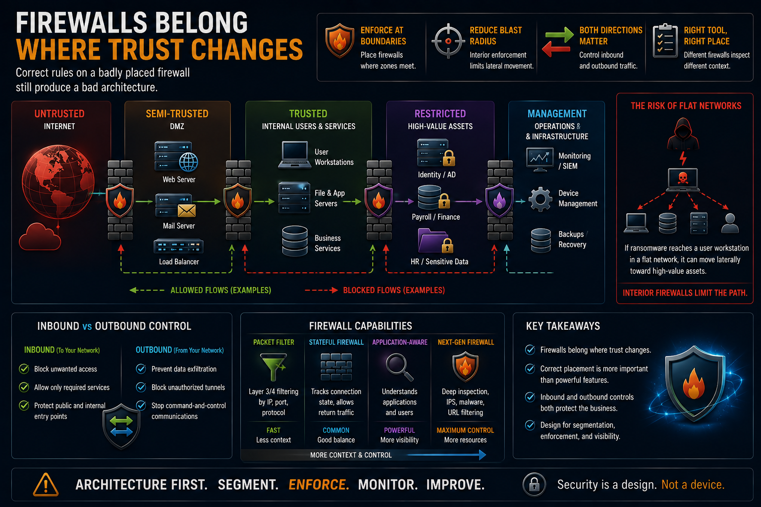
The internet edge matters, but it is not enough. If ransomware reaches a user workstation and the internal network is flat, a strong perimeter firewall does little to stop lateral movement toward payroll or identity systems.
Interior enforcement limits that path.
Direction matters in both ways. Inbound rules receive most of the attention. Outbound controls can interrupt exfiltration, unauthorized tunnels, and command-and-control traffic.
Packet filters, stateful firewalls, and application-aware firewalls inspect different amounts of context and cost different amounts of capacity and operational effort. This post places the enforcement point and writes the first rule. Deeper rulebase engineering, proxies, TLS inspection, and high availability belong in the firewall material.
ACLs evaluate top to bottom and stop at the first match
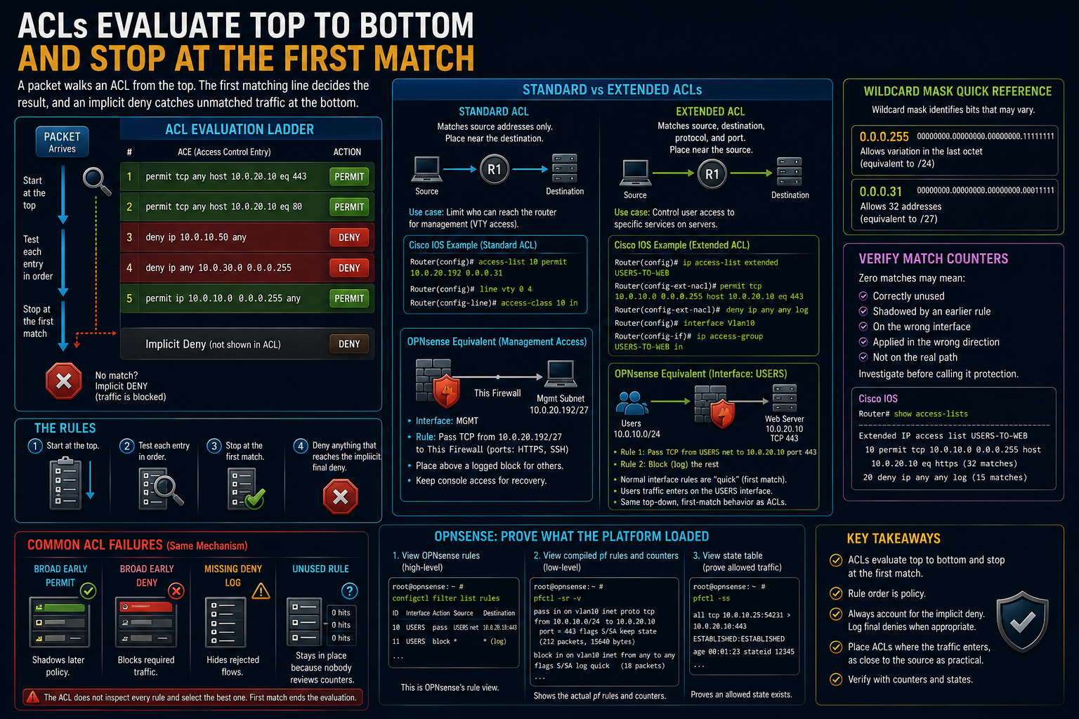
A vertical list of ACL entries shows a packet testing each entry in order, taking the first permit or deny action, with an implicit deny below the visible list.
ACL evaluation is simple enough to state and important enough to repeat:
- Start at the top.
- Test each entry in order.
- Stop at the first match.
- Deny anything that reaches the implicit final deny.
Rule order is policy. A broad permit above a narrow deny can make the deny unreachable. A broad deny above the required permit can create an outage.
The implicit deny may not produce the evidence you need. Add an explicit final deny with logging when the platform and traffic volume support it, then monitor the result so the logging itself does not become a denial-of-service path.
Common ACL failures are variations of the same mechanism:
- A broad early permit shadows later policy.
- A broad early deny blocks required traffic.
- A missing deny log hides rejected flows.
- An unused rule remains in place because nobody reviews counters.
The ACL does not inspect every rule and select the best one. First match ends the evaluation.
Standard and extended ACLs
A standard IPv4 ACL matches source addresses. The traditional placement rule is near the destination because it cannot distinguish applications or destination addresses.
The following example limits router CLI access to the management subnet from the addressing plan.
[Cisco IOS shown]
Router(config)# access-list 10 permit 10.0.20.192 0.0.0.31
Router(config)# line vty 0 4
Router(config-line)# access-class 10 in
OPNsense does not attach a standard ACL to a VTY line. Express the same intent as a firewall rule on the management interface: source 10.0.20.192/27, destination This Firewall, protocol TCP, and only the enabled management ports, normally HTTPS and SSH when SSH is required. Place the rule above a logged block for other management access. Keep the console recovery path available before applying the restriction.
An extended ACL can match source, destination, protocol, and port. Place it near the source when practical so unwanted traffic is rejected early.
[Cisco IOS shown]
Router(config)# ip access-list extended USERS-TO-WEB
Router(config-ext-nacl)# permit tcp 10.0.10.0 0.0.0.255 host 10.0.20.10 eq 443
Router(config-ext-nacl)# deny ip any any log
Router(config)# interface Vlan10
Router(config-if)# ip access-group USERS-TO-WEB in
On OPNsense, add the equivalent pass rule under Firewall > Rules > USERS because user traffic enters the firewall on that interface. Set source to USERS net, destination to 10.0.20.10, protocol TCP, and destination port 443. Add a logged block below it for the remaining user-to-server traffic. Normal interface rules are generated with quick, so the operator sees the same top-down, first-match behavior taught by the ACL example.
Inspect the generated policy and resulting state from the shell:
[OPNsense 26.7 shell shown]
root@opnsense:~ # configctl filter list rules
root@opnsense:~ # pfctl -sr -v
root@opnsense:~ # pfctl -ss
configctl filter list rules asks OPNsense for its rule view. pfctl -sr -v shows the compiled pf rules and counters. pfctl -ss proves that an allowed state exists. Configure the rules in OPNsense, then use the shell to prove what the platform loaded.
The wildcard mask identifies bits that may vary. 0.0.0.255 permits variation in the final octet. 0.0.0.31 corresponds to the 32-address /27 management block.
Verify match counters:
Router# show access-lists
A rule with zero matches may be correctly unused. It may also be shadowed, placed on the wrong interface, applied in the wrong direction, or disconnected from the real path. Investigate before calling it protection.
Rogue DHCP wins by answering first
A DHCP client begins without an address and broadcasts a Discover. A server sends an Offer. The client broadcasts a Request selecting one offer, and the chosen server returns an Acknowledgment.
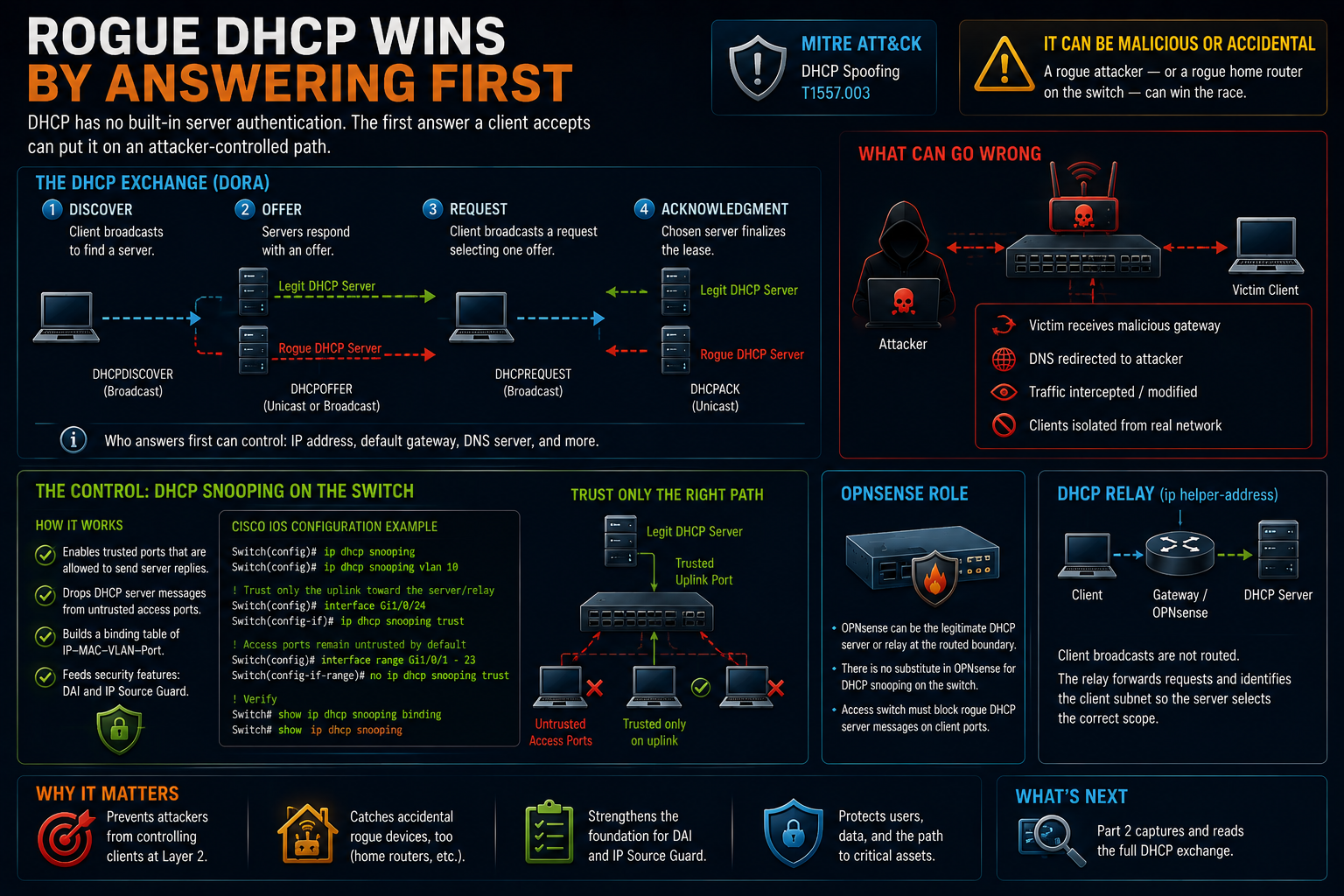
There is no built-in server authentication in that exchange. A rogue server can answer quickly and provide an attacker-controlled gateway or DNS server, placing victims on a path the attacker controls. MITRE ATT&CK identifies this as DHCP Spoofing, T1557.003.
The same failure can be accidental. Someone connects a home router to an office switch, and its DHCP service begins answering clients. A useful control catches both malicious and accidental violations.
DHCP snooping marks which switch ports may receive legitimate server messages. Offers arriving from untrusted access ports are dropped and logged.
Clients use broadcasts, and routers do not forward those broadcasts normally. A DHCP relay on the client gateway forwards the request to the central server and identifies the client subnet so the server selects the correct scope.
[Cisco IOS shown]
Switch(config)# ip dhcp snooping
Switch(config)# ip dhcp snooping vlan 10
Switch(config)# interface Gi1/0/24
Switch(config-if)# ip dhcp snooping trust
Trust only the path toward the legitimate server or relay. Do not mark user-facing access ports trusted.
There is no OPNsense substitute for this switch configuration. OPNsense may be the legitimate DHCP server or relay at the routed boundary, but the access switch must reject server messages arriving from untrusted client ports.
The binding table created by DHCP snooping is the same table Dynamic ARP Inspection and IP Source Guard use. You now know who builds it and why its accuracy matters.
Part 2 captures and reads the full DHCP exchange.
First exercises: routing and enforcement
Exercise 1: route between the VLANs
Use router-on-a-stick or switched virtual interfaces. Explain why you chose it.
Repeat the cross-VLAN test that failed earlier and prove that routing now succeeds.
Exercise 2: permit one application flow
Write one extended ACL that permits users to reach one server on TCP 443. Add an explicit deny with logging and apply the ACL inbound on the user VLAN.
Exercise 3: prove both outcomes
Collect four pieces of evidence:
- A TCP 443 connection to the permitted server succeeds.
- Another flow not allowed by the ACL fails.
show access-listsshows the permit counter increasing.- The deny counter and log entry increase for the rejected flow.
When OPNsense is the enforcement point, use pfctl -sr -v for rule counters, pfctl -ss for the permitted state, and Firewall > Log Files > Live View for the rejected flow. Test both outcomes exactly as you would for the router ACL.
Do not use ping as proof of the permitted HTTPS rule unless the ACL also permits ICMP. Test the protocol the rule actually allows.
Save the deny event beside the port-security event. The file is becoming a small evidence pipeline.
Where Part 1 leaves you
You can now read an addressing plan, trace a frame through a switch, explain a trunk, predict spanning-tree behavior, read a routing table, and place a policy control at a chokepoint you built deliberately.
Your evidence file contains two events you caused:
- A port-security violation
- An ACL denial
Part 2, Watching the Network You Built begins there. It covers DHCP, DNS, NTP, TLS, network monitoring, wireless, remote access, and the path from individual log lines to a monitoring pipeline.
It also returns to the packet walk. The first diagram showed the path clean. The final diagram will show each control at the point where its traffic must pass.
The violation event is not homework theater. It is input for the monitoring system, and Part 2 will prove it.


